This is not quite a printer printing itself but just as impressive, the real use case of using 3D printing in a critical way during product development – functional prototypes that can be used in the printer.
All design work on the ARKe was completed in SOLIDWORKS as we are a Solid Works solutions partner. The system allowed us to collaborate not only internally amongst our own engineering team but internationally with our manufacturing partners and suppliers.
During initial product development certain parts needed to be tested before ordering tooling or large quantities for production. These are commonly long lead items so being able to prototype these parts and then check the design for function, form and fit saved time and money during the development process – this is when 3D printing comes into its own.
For the purposes of this blog I will outline just some of the parts that were designed in SOLIDWORKS and then printed and tested in the ARKe during the design phase of product development.
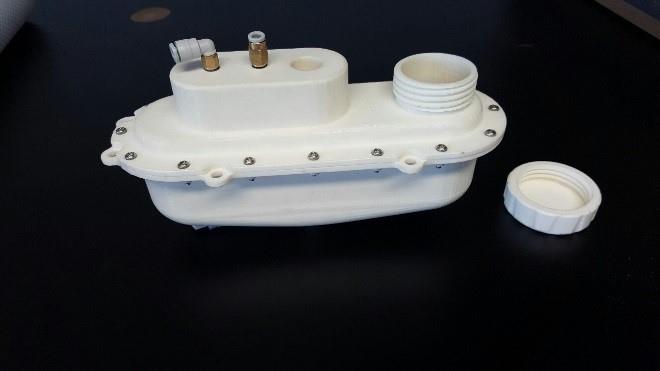
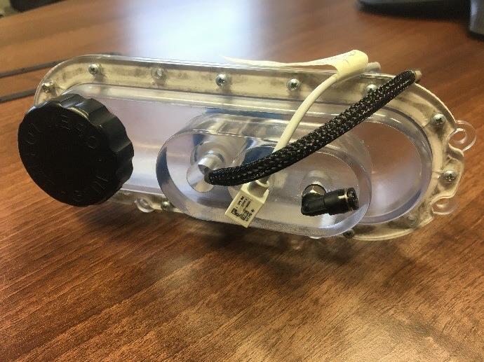
Glue bottle system
 For the glue bottle system, we needed to make sure that the lid was easy to access and that it was easy to open and close. We 3D printed the part with the threads included so that we could test this. When we finally got the production parts in we double checked our initial testing by confirming the production lid would screw into the printed bottle and vice versa. Along with printing the threads of the glue bottle lid we printed holes along the joining faces of the bottle slightly smaller than the self-tapping screws we planned on using. Once post-processed we were able to thread the printed part with the self-tapping screws. A third method of tapping screw holes on this prototype was used for the glue pressure sensor where we again printed a hole in the part but used a traditional tap to add the threads we required. The printed part also ensured we left enough clearance inside the printer for the bottle to fit.
Gasket 
A gasket was designed to fit between the two bottle halves; this was drawn in SOLIDWORKS and the eDrawing was converted to a PDF which was then converted to a vector drawing in Inkscape in order to have the part laser cut. Before ordering the laser cut parts we were able to double check the size was correct by converting the SVG file into an STL using tinkercad. This also ensured that nothing had been lost in translation while bouncing between SOLIDWORKS, drawings, a PDF and the vector drawing.
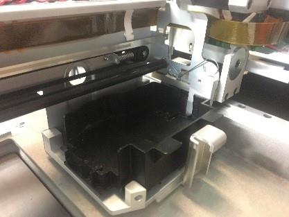
Maintenance tray
 The maintenance tray sits on the 2D print bar and houses the print heads when not in use. It is designed to be removable and we had to design a bracket that would allow us to slot the tray in and out easily. In order to test this bracket in place before receiving the production trays we were able to print the SOLIDWORKS model and test for a tight, secure fit and access to the area for users to easily remove and replace the part.
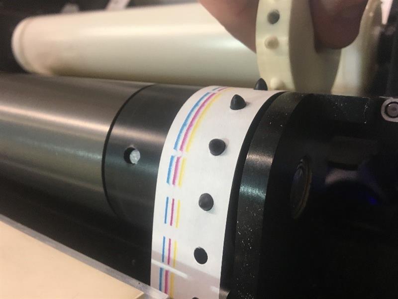
Pin wheel
The pin wheel in the paper feed is critically accurate to feeding the paper so we had to ensure that the pins aligned with the holes of the paper. By printing this part first on our 3D printers we could make sure the alignment was correct. We also were able to ensure that the bar on which it sits was able to clear the through hole without too much play and that the grub screw through the pin wheel would secure it in place on the bar well enough not to slip during the operation.
3D printing is an integral part of any design process especially a design with over 1000 parts in it.It may not be a self-replicating printer just yet but it sure helped in a very functional way in the development of the ARKe.


