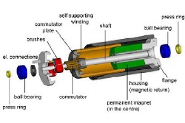
All DC motors are built of three main sub-assemblies; the stator, the rotor and the brush system. The main body of the motor is the stator, consisting of the permanent magnet which is centrally located around the shaft, within the housing and the mounting flange. The permanent magnet is diametrically magnetised with a North Pole and South Pole. The magnet has a bore hole for the shaft of the motor. The magnetic induction comes out the North Pole into the housing and out into the magnets South Pole. The housing is made of magnetically conductive material and acts as magnetic return.
There is an air gap between the permanent magnet and the housing. This creates a strong magnetic field to ensure the winding produces as much force as possible. Too much of an air gap weakens the magnetic flux as air is a bad magnetic conductor. Finding the optimum air gap is always difficult as it depends strongly on the properties of the permanent magnet. Keeping the air gap too narrow only allows a thin winding, which restricts lower current density and produces a reduced power density.

Figure 1 - Exploded view of a brushed DC motor
The rotor is made of the winding and the commutator and this allows the shaft to rotate. In the centre of the motor is the shaft, made of hardened steel, to withstand loads for the application, given that the correct motor has been selected. The commutator plate holds the commutator bars and the plate is fixed onto the shaft by plastic moulding. On the outer diameter of the commutating plate is the self-supporting coreless winding, which is fixed via the welding of contacts to the commutator bars. Glue covers the contacts and welding, giving it mechanical strength. Typically, there can be seven commutator bars and winding segments. The more bars and segments, the smaller the amount of energy must be switched during commutation, which increases service life due to reduced brush fires. Torque produced in the winding will be transferred via the commutator plate to the shaft and this is supported in the stator with either sleeve or ball bearings.
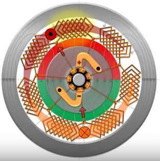
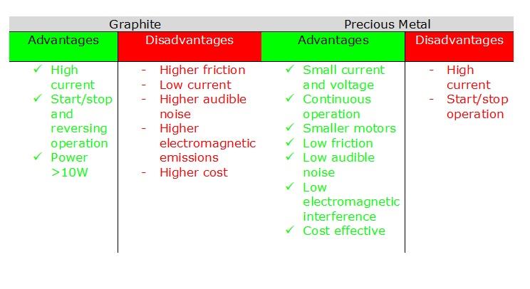
Finally, the brush system. They can either be graphite or precious metal brushes which have electrical motor connections. To supply power to the rotor we put in place a brush system and each of the brushes have a direct voltage symbol (+/-). The brushes are connected to the commutator bars which allows the current to flow into the winding. Then two rhombic shaped currents appear near the centre of the poles opposite and in between the winding segments in the magnetic field. The rhombuses are continuously attracted to the strongest magnetic flux causing the rotor to rotate, but due to the odd number of commutator bars, they both can never meet at the direct opposite poles. Therefore, the rhombuses keep switching into the space in the next approaching segment. This continuously occurs, producing the torque of the motor.

Figure 3 - Commutation

Why are there brushless motors?
As you may already know there are brushless DC motors. So, are they needed? Well, there are some advantages and they are becoming increasingly popular world-wide. This is mainly to do with lifespan. Basically, they have no brushes to wear out. Brushless motors commutate electronically, therefore it is more complex which means that they require more equipment to run, such as a computer, controller software, controller, wiring/cabling and encoders in most cases. In addition, you need an understanding of the software.
Brushed DC motors only need a DC power supply, two cables and for it to be connected to the motor terminals.
Choosing the wrong motor can be an expensive mistake. To make sure this doesn’t happen contact us to discuss your application salesuk@maxonmotor.co.uk or 01189 7833 337.
Author profile:
Patrick Vega, Technical Engineer at maxon motor uk


